
Accelerate Wind
I spent the summer between my sophomore and Junior year of undergrad living and working at Argonne National Laboratory for the startup Accelerate Wind.
As air flows over the top edge of a building, it accelerates, providing a promising opportunity for energy capture. However, this fast flow occurs about 40 feet above the rooftop, where it becomes cumbersome and ugly to place a turbine. The goal of this internship’s research was to find a solution to this issue.

To find this solution, over 250 airflow simulations were run on a wide range of different 3D models. These models and simulations were created using the software Onshape and Simscale respectively. The 3D models consisted of shapes that could be easily placed on a commercial building’s edge, thus modifying the airflow over the building. Using an iterative process, these 3D models were refined to effectively bring this fast airflow closer to the building’s rooftop. After a few promising results were found, one was chosen and a manufacturable prototype was designed, and rigorously safety checked.
For the remainder of the summer the prototype began its manufacturing process, and should be installed on a rooftop for testing by October 2019. If the results are promising, this summer’s work could do a great deal to bring renewable energy to urban areas. This research was carried out as a collaboration of Argonne National Laboratory and Accelerate Wind, a wind energy company focused on creating cheap rooftop wind energy for commercial buildings.
Process:
Computational Fluid Dynamics:
To find this solution, over 250 airflow simulations were run on a wide range of different 3D models. These models and simulations were created using the software Onshape and Simscale respectively. The 3D models consisted of shapes that could be easily placed on a commercial building’s edge, thus modifying the airflow over the building. Using an iterative process, these 3D models were refined to effectively bring this fast airflow closer to the building’s rooftop. After a few promising results were found, one was chosen and a manufacturable prototype was designed, and rigorously safety checked.
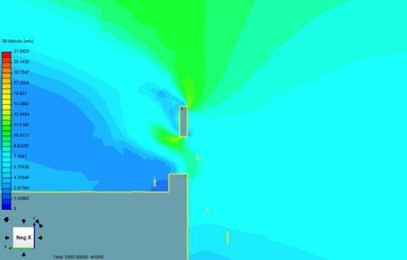
Simple Simulations:
We began our experimentation on a variety of very simple shapes to build intuition for how the air flows over the building. Some examples are shown below:
Simple Gap Simulation
Simple Slope Simulation
Simple Rod Simulation
Back End Wall Simulation
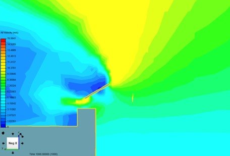
After building this intuition and learning how to better use the software, we moved on to more complex designs. The designs broke down into three main strategies: airfoils, ducting, and aerospikes. We also later added a category that worked via pressure differential. Some examples are shown below:
Complex Simulations:

Aerospike Model Example
Aerospike Simulation Example
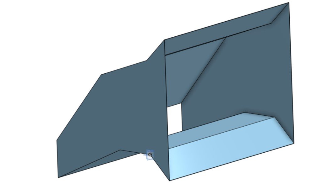
Duct Model Example

Duct Example Simulation
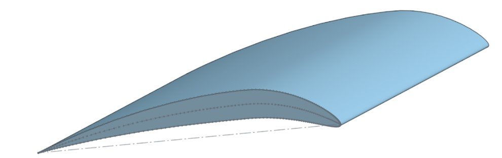
Airfoil Model Example 1

Airfoil Simulation Example 1
Airfoil Model Example 2
Airfoil Simulation Example 2
In this phase we combined multiple strategies in an attempt to lower the high velocity air with a system of parts rather than just one. Examples shown below:
Combined Simulations:
Double Airfoil Example

Double Airfoil with Duct Example

Airfoil/Aerospike Combination
Revolved Airfoil Duct

Revolved Airfoil Duct Simulation
We found a few designs that yielded wind velocities around 12-13 meters per second, with that air flowing over/through each structure sufficiently far and with enough volume to collide with a 2 meter diameter turbine. With these designs in mind, and with our insights and data from our great many simulations, we proceeded to the next stage in the prototyping process.
Results:
Prototype Design:
With multiple strategies succeeding in CFD simulations, we originally planned to prototype each and test them on the roof of Argonne’s building 212. Such giant structures would need to be manufactured, assembled, and installed safely and carefully. We planned to design a frame which would be mounted to the roof, and to be compatible with each successful wind-affecting structure. However, when we ran preliminary force and torque calculations on such a system, we found many forces to be too great to reasonably mount onto our roof. The upper air foil, in particular, generated a great deal of lift, and generated far too much torque on the system overall.
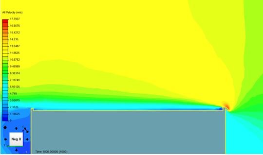
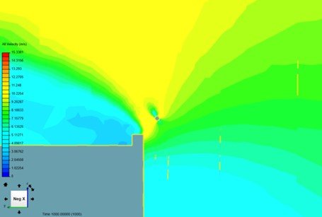
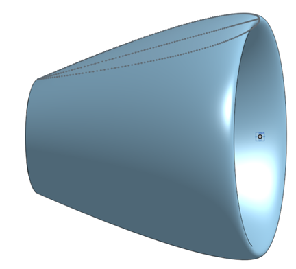
We decided instead to focus on creating a design for just one wind-affecting structure, and a simpler mounting frame that would be more reasonable within the time left in our internship, and so we settled upon trying to mount a design called “aerospike 32”, since this structure’s estimated wind drag and lift were lowest, and the structure itself would lend itself most readily to prototyping.

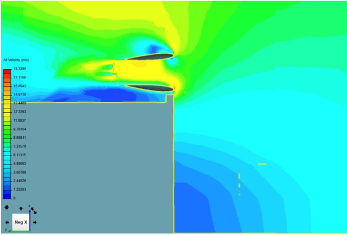
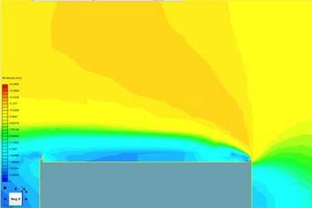
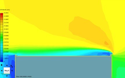
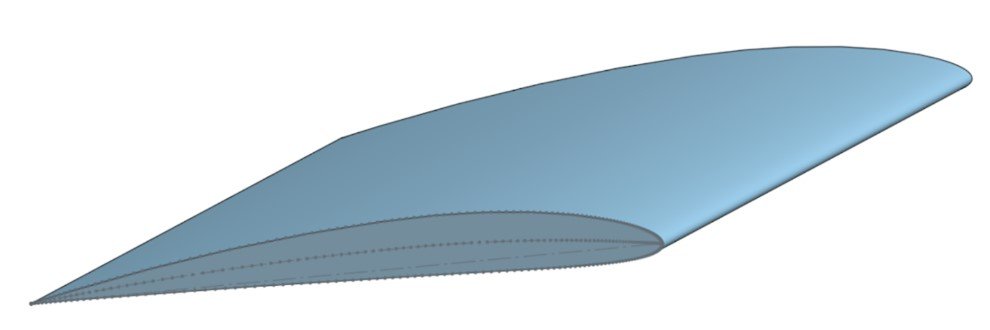
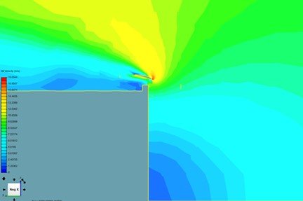
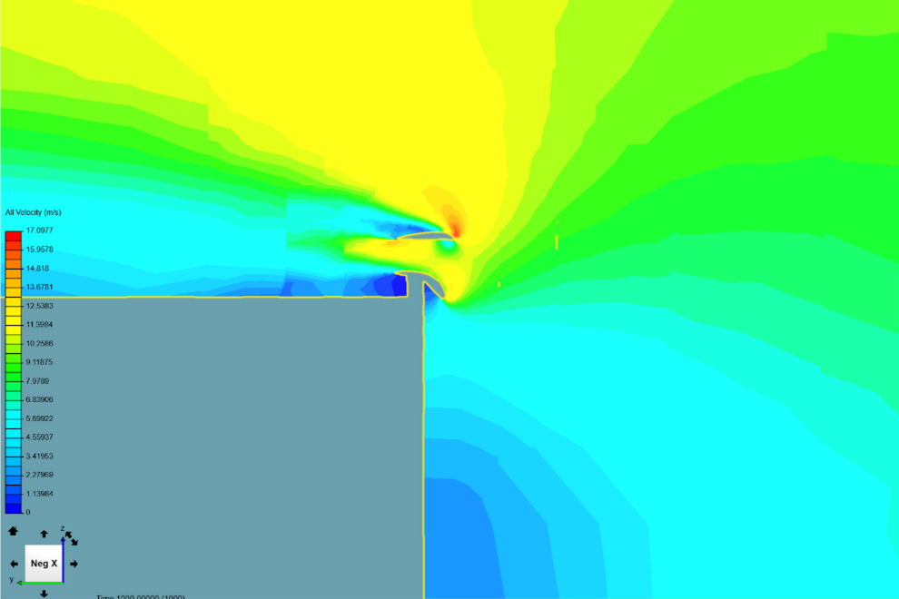
"Aerospike 32" Simulation

"Aerospike 32" Simulation Zoomed
At the beginning of the prototyping process, our two main concerns were ease of manufacture and cost. Since Aerospike 32 is vaguely wing shaped, we took our inspiration from there. We came up with two preliminary ideas. One using a “ribs and stringers” design, the other using “ribs and foam”
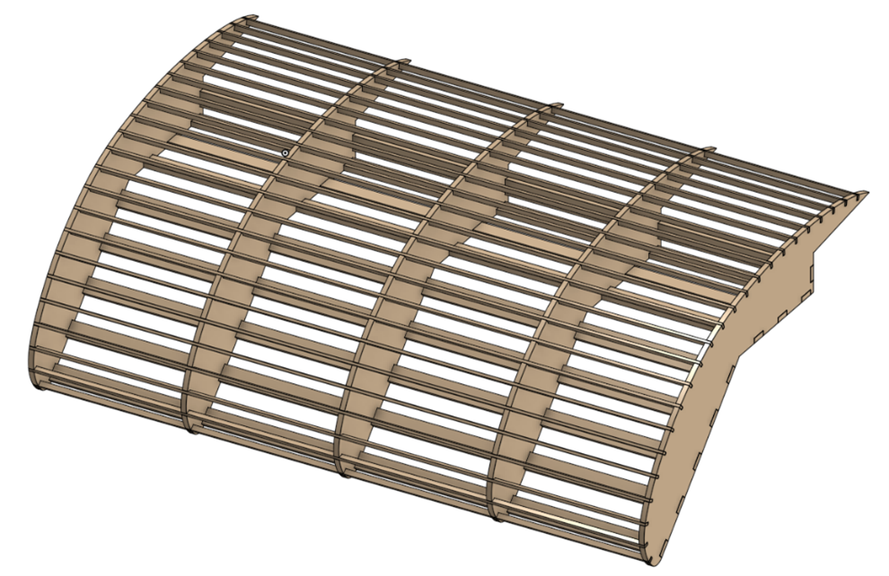
Ribs and Stringers Design
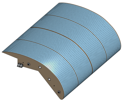
Ribs and Foam Design
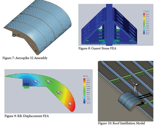
In the end, we ended up moving forward with the ribs and foam design due to the ease of manufacture, lower material cost, and its lower weight. After this decision was made the design was more fine tuned and prepared for actual manufacturing. The final design was 10ft long and the dimensions of its cross section are shown below
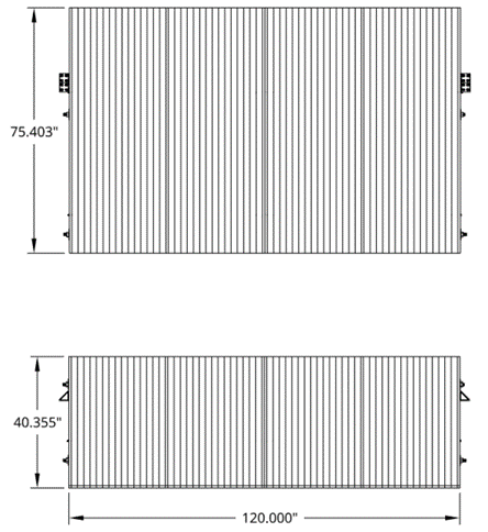
Prototype Dimensions
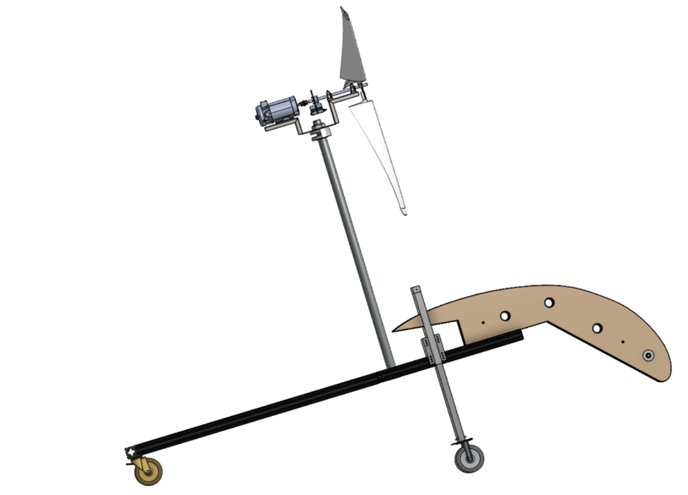
Prototype with turbine
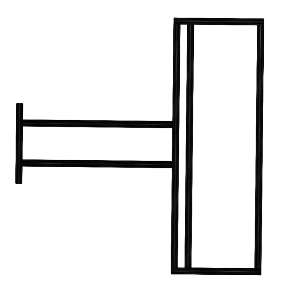
Prototype Mounting Frame

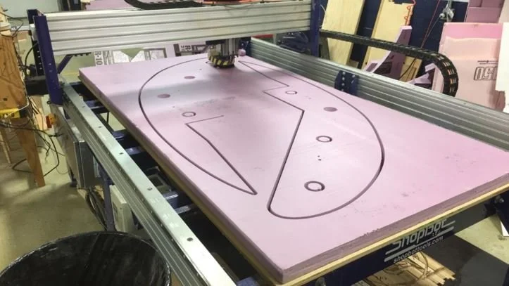
Fabrication:
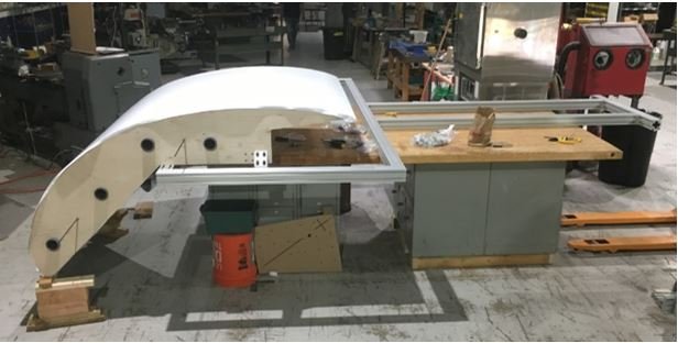
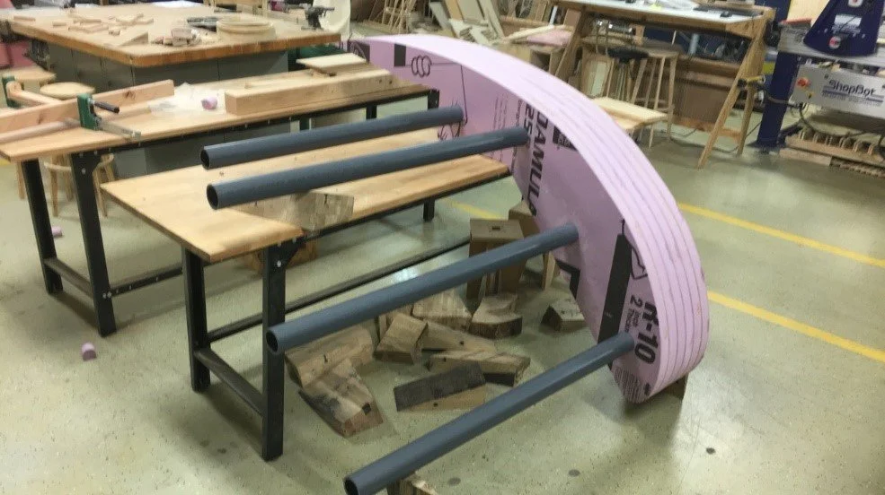
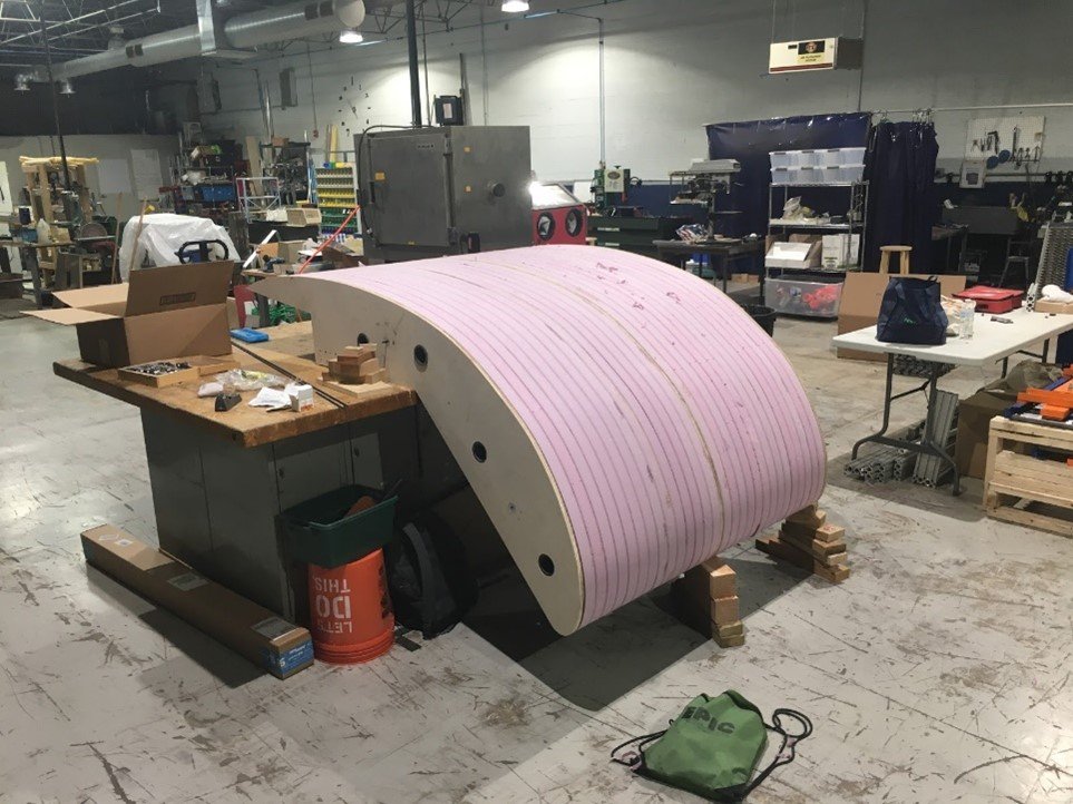
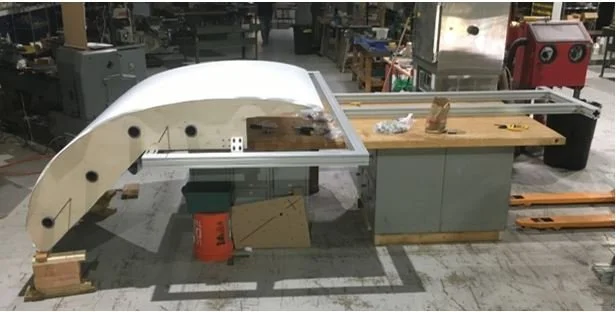
After the design was completed and thoroughly analyzed we moved on to fabricating a 5ft prototype. This was done in order to find any design oversights before manufacturing the entire 10ft assembly. We worked at the “makerspace” called Make-it-Here in Downers Grove, IL.
The foam and wood sections were cut on a ShopBot, and all the other components were ordered to size or cut to size with hand tools.
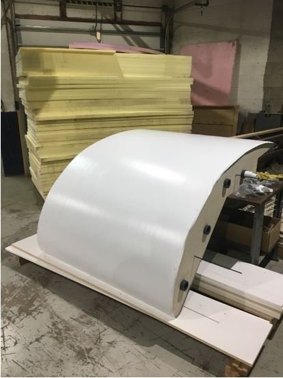
After the prototype was assembled, it was covered with vinyl and heated to shrink it to fit the frame.
Below are some images of the prototype’s manufacturing process:

Results:
At the end of this Summer’s research we find ourselves in a promising position. Our first prototype was assembled, mounted to its frame, and ready for rooftop testing. We have redesigned aerospike 32 with these modifications and this second prototype is ready to be manufactured.